MILLER FILTER
S O L I D S R E C O V E R Y
LARGE SCALE SOLIDS
RECOVERY OPERATIONS
Contents of this chapter:
- STATE-of-the-ART
1. MILLER
UNI-SOLIDS SYSTEM
2. MILLER
FILTER TUNNEL DRIER
3. MILLER FILTER VACUUM DRIER
4.
MILLER CAKE PRESS VACUUM
DRIER
STATE-of-the-ART
The following chart
exemplifies a variety of filter apparatus used for SOLIDS RECOVERY
OPERATIONS. Many are derived for the originating NUTSCHE but a
sizeable proportion is based on the FILTER PRESS and the BASKET TYPE
CENTRIFUGE.
 Almost a
century ago the ROTARY VACUUM FILTER improved significantly the
performance of the above depicted GRAVITY & VACUUM NUTSCHE.
Almost a
century ago the ROTARY VACUUM FILTER improved significantly the
performance of the above depicted GRAVITY & VACUUM NUTSCHE.
Much higher throughputs with
far less labour were achieved. The open design, cake instability, poor cake
washing and lack of control are major drawbacks.
The horizontal VACUUM BELT FILTER, solved many of these
problems. However the exposed design and lack of CONTROL have
prevented the general acceptance of these types of filters in many industries.
This disadvantage of exposed
design was overcome by the development of the PRESSURE NUTSCHE which
provided completely sealed operation. This advantage was however offset by safety
problems, lack of accessibility as well as CONTROL and difficult
mechanical solids removal from the sealed container.
The BELT MEMBRANE PRESS
after a period of popularity, e.g. in the chemical and sugar industry, has lost
ground due to the lack of the means of CONTROL, mechanical complexity,
chamber sealing problems and the exposed design.
The CENTRIFUGE FILTER
fitted with mechanized retractable media for ease of cake removal has found a
niche application in the multi-product pharmaceutical and fine chemical
industries. Drawbacks involve safety considerations inherent mechanical and CONTROL problems.
The MILLER FILTER has proven itself as an ideal apparatus for recovering
solids from suspensions in many industries.
The following examples provide an overview of the wider range of
possibilities accruing from this unique mono-planar design principle
showing that a universal application accompanied by full automation and
an environmentally friendly operation is in the offing.
1.
MILLER
UNI-SOLIDS SYSTEM
Many solids recovery operations involve the formation of thin adhesive
cakes which prior art apparatus can handle only with the expenditure of
excessive manual labour.
The MILLER UNIVERSAL SYSTEM utilizing SHUTTLE expanded surface elements
provides fully automatic solutions to these and a host of other challenging
solids recovery operations.
OPERATION
·
After primary filtration in
the CENTRE SECTION (1) the residues within the elements are de-watered.
·
With the chambers opened the
belt transports the element (1) through CHAMBER 2 . On passing around the
deflection roller the fin-shaped elements flare (open up) and with a
simultaneous jolting action of the swing-jointed rollers the solids are
dislodged into the skip below.
·
Inevitably traces of solids
remain in the elements. It is essential to remove and recover these
(regeneration) after each cycle. The direction of travel of the belt is now
reversed. The previously regenerated element now in (2) is transported into (1)
while the soiled element now above the solids container is transported into
(2).
All chambers are now sealed.
UNIVERSAL SOLIDS RECOVERY SYSTEM
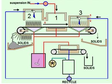
·
Primary filtration in the
CENTRE SECTION (1) is resumed.
·
The soiled element (2)
is subjected to mobile high-pressure jets of cleaning fluid. The extra
provision of ULTRA-SONIC cleaning is an added option.
·
The suspensions generated are
collected and filtered in a standard MILLER solids recovery filter whereby the
filtered liquid is recycled to the SHUTTLE for further element regeneration.
·
On the following cycle the
used element in (1) is transported to the right hand side of the SHUTTLE for
solids removal and regeneration in (3) while the previously regenerated element
in (2) is transported to (1) for the next filtration operation.
CAPACITY
Individual SHUTTLE ELEMENTS
are fitted with up to 200m2 filter area which operating on
cycle times of 20-40 minutes can achieve through-puts far in excess of prior
art apparatus.
THE MILLER FILTER CONCEPT LED
TO ITS UNIQUE COMBINATION AS A
FILTER-DRIER
2. MILLER
FILTER TUNNEL DRIER
The MILLER TUNNEL DRIER is ideal for higher melting point solids
that can be directly contacted with hot gases.
OPERATION
·
The suspension is pumped
through a standard Miller Filter forming a filter cake that is finally
partially de-watered under vacuum.
·
The cake is transported on a
section of filter belt into the TUNNEL DRIER while the final section of cake
already in the drier is discharged as a dried powder to a storage container.
The heated gas input is shut down during the transportation.
MILLER FILTER TUNNEL DRIER
·
The tunnel is resealed and
the next drying cycle proceeds.
·
During the belt transport a
section of belt is washed whereby solids residues on the band are recycled to
the suspension tank.
·
Contained sealed plants with
up to 10m2 of filter area and 20m2 of drying area are
available for fully automatic round-the-clock operation.
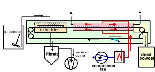
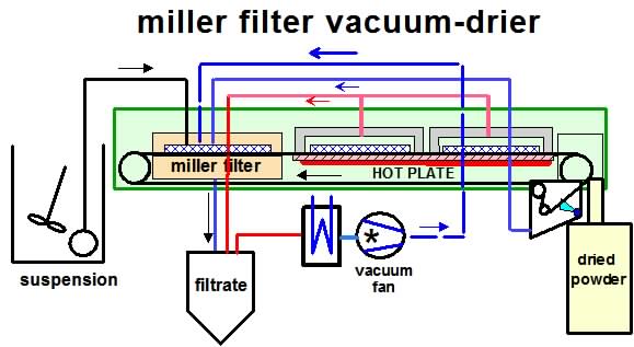
3. MILLER
FILTER VACUUM DRIER
Especially suited for recovery of heat sensitive solids from
suspension in volatile solvents common in pharmaceutical, chemical and
food production processes.
OPERATION
·
The filter cake is transported
on the filter belt from the Miller Filter to the VACUUM CHAMBERS.
These chambers have a similar design to the Miller Filter.
The cakes and belt sections are supported on a HOT PLATE held at
temperatures below the melting point of the solids.
The filter chambers are sealed and made vacuum tight thus forming two
independent vacuum cake drying containers.
·
Vacuum is applied to both drying
chambers and on reaching a set value the drying chamber nearest the
MILLER FILTER is isolated from the source of vacuum.
·
On attaining a maximum
under-pressure in the end drying chamber the source of vacuum is
isolated from all chambers, after which they are all vented to the surrounding
sealed housing and opened.
·
The belt simultaneously
transports all three cakes forward thus
1.
discharging the solvent free end
cake to the dried powder container,
2.
transporting the filter cake
in the MILLER FILTER to the first drying chamber and
3.
transporting the partially
solvent free cake in the first drying chamber to the second drying chamber.
-the cycle is then repeated-
4.
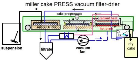
MILLER
CAKE PRESS VACUUM DRIER
Many aqueous suspensions
requiring dewatering in industrial and municipal processes produce compressible
residues prone to crack-building with conventional dewatering methods. Such residues are often the cause of
insuperable transporting, further processing and handling difficulties.
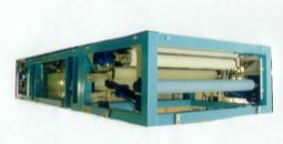
The MILLER SOLUTION to these problems is a TANDEM MULTI-MODE DEWATERING
MACHINE.
OPERATION
·
FILTRATION
Suspension is filtered under positive pressure in the MILLER FILTER forming a
partially de-watered filter cake.
·
CAKE PRESSING
The partially de-watered cake is transported into the second compartment
where it is subjected to mechanical compression by means of a top horizontally
mounted hydraulically actuated thick
metal plate the surface of which is treated with PTFE and fitted with a special
peripheral sealing device. The plate is lowered slowly and incrementally on to
the surface of the cake allowing sufficient time to counter the increasing
resistance with time to the seepage of liquid through the cake.
·
CAKE DRYING
In the third compartment a combination of lower hot plate
and upper radiant heat supported by vacuum ensures
a rapid cake-drying process.
If necessary the solidified cake can be broken into pieces on discharge.
In practice all three operations described above take place simultaneously and
fully automatically.
-the cycle is then repeated-
p.a.miller2@btopenworld.com